Tuned mass damper with damped mass far away from point of interest
Precision analysis equipment such as Scanning Electron Microscopes are nowadays regularly installed close to or in a fabrication environment, such as the IC industry in a clean room. This setting however implies an increased acoustic and floor vibration noise level, leading to compromised microscope images. In the case of a SEM the resolution is limited by the high acoustic sensitivity in only one narrow frequency band, originating from the resonance of the stage. By the application of a Tuned Mass Damper (TMD) in this microscope, the specific peak of the sensitivity can be largely suppressed.
Principle
In the case of a SEM electron microscope the amplitude of the vibration mode is ‘largest’ at the end effector near the sample; typical amplitudes are already sub nm. Ideally a TMD should be located at this end effector. However, the space for a TMD is limited there. Therefore the TMD is located close to the base. Amplitudes at the base are even a few orders of magnitude smaller then at the end effector! Therefore the TMD mass must be proportionally heavier to become similarly effective compared to when it could be at the end effector. But since the space is available there the problematic vibration at the end effector can be damped even far away from this end effector.
Background
A Tuned Mass Damper (TMD) is a device mounted in structures to reduce mechanical vibrations. It consists of a mass mounted on one or more damped springs. Its oscillation frequency is tuned to be similar, or almost similar, to the resonant frequency of the object it is mounted to. It therefore picks up energy from the vibration mode of the structure and vibrates with the structure. The damper reduces the amplitude of tuned mass in the first place. It therefore dissipates energy from the complete system and reduces the amplitude of the vibration mode of the structure. Tuned mass dampers have been reported as early as the mid-1950s for example for reducing the unpleasant vibration of the housing of a hair-clipper [1]. Typically a TMD is placed near the location where the amplitude of a vibration mode is large, the antinode, in which case the mass of the TMD can be much lower than the object’s mass.
Tuned Mass Damper concept in an electron microscope
However, in the case of the electron microscope there is limited space near the end effector m6 and there must be space available to mount the damper m7 in an existing stage, which requires the TMD to be located closer to the base at m2 [2]. A consequence of the near base-mounting and the high resolution of the apparatus is the extremely small amplitude of the vibrations, which are far below the nanometer range, in the order of a few 10 pm’s. The nanometer ‘magnitude’ of vibrations at the end effector only causes fully elastic deformation; it is simply too small to consider (non-linear) friction-like damping concepts with relative motion of bodies. This is proved by the fact that the stage even contains numerous elements like bearings and cages which definitely would exhibit non-linear friction damping, but the general observation in modal measurements using a shaker is a very ideal linear behavior up to several tens of nm’s. Non-viscous or ‘friction’ damping, so bolted instead of welded frames, an intentional loose rattling part, a small clearance, a bag of sand, is therefore not usable for this application. A viscous type of damping, like TMD, is therefore the only option.
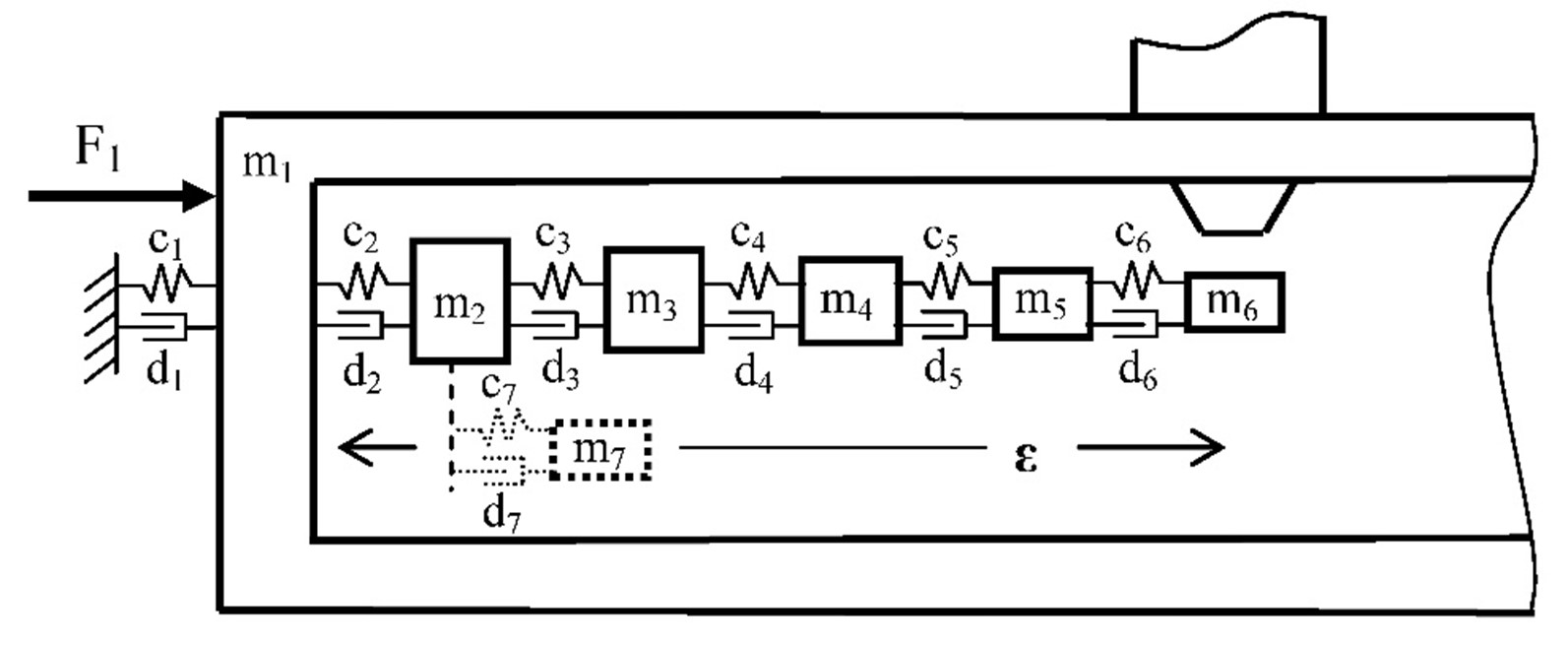
Figure 1. Dynamic model of microscope system. m1 is the chamber, m2 to m6 are the carriages, becoming successively lighter of mass. m7 is the Tuned Damper, to be attached to m2 .
Modal analysis has proved that the stage carriages almost do not deform internally: the compliance is traced between the carriages. In this case it will not help to make the carriages from a well-damped material because there is no vibration energy to be damped. Only (series-) damping between the carriages can be effective.
As a consequence of the large sample and complicated stage, the masses of the (lower) carriages are in the several tens kg range, see Figure 1. The realized stiffness resulting in a 183 Hz resonance may be called an achievement already. The higher the combination of stiffness and mass, the higher the critical damping dc = 2√(mc) . To achieve significant relative damping ζ =d/dc , the absolute damping d to must be high as well (order of 104 Ns/m!).
The Tuned Damper principle has the general advantage that a small frequency band, just on a sensitivity, can be effectively damped by a relatively small auxiliary mass, typically about 1/3 of the to be damped mass . But the following advantages, typically related to the application in the field of electron microscopy, really make the Tuned Damper to excel:
– It may be attached to one element of the system. The damper can thus be put in a hermetically sealed enclosure, e.g. a closed air-chamber within the vacuum chamber. This solves all vacuum compatibility problems!
– As a consequence of the mass-ratio, the absolute damping required for the auxiliary mass becomes realistic.
– Easy retrofittable in current systems in the field.
– Industrial implementation is feasible, no tuning per system is required.
Realization of the Tuned Mass Damper
The construction, which was chosen to be the most suitable, is shown in Figure 2, with only one end drawn. The complete damper construction will be inserted in the available long hole of the tilt bridge and firmly clamped to the inner-wall by a simple clamping device (not drawn here).
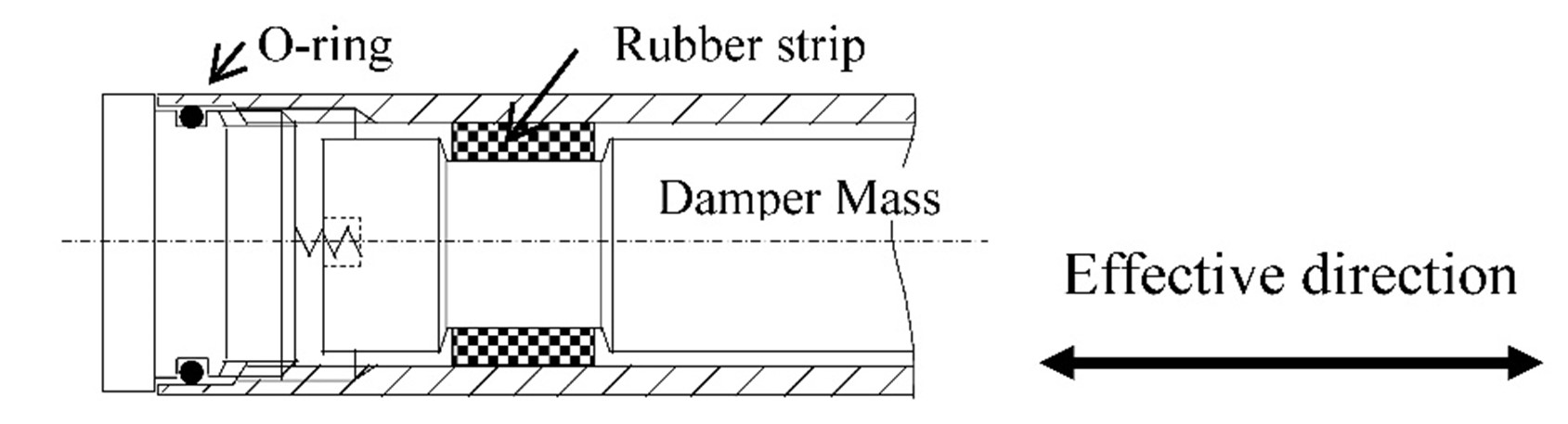
Figure 2. Tuned Damper construction
The construction consists of an air chamber from a Ø50 mm thin-walled Al pipe, vacuum-closed by two caps, carrying O-rings. The damper mass in the pipe is a massive, 400 mm long cylinder from the heavy Wolfram alloy Densimet (density 17800 kg/m3 ), chosen to achieve the desired mass-ratio; its mass is 9.23 kg. A rubber material, which was found to have both good elastic properties and significant, absolutely viscous damping properties (at nm amplitude) was K1077 fluor silicon rubber. Strips of 3 mm thick are folded around the Damper mass, in turned-out sections at both ends of the shaft. The diameter of the sections is made such that, when pushed into the Al pipe, the rubber strips are compressed up to a predetermined rate! The strips provide the support of the damper mass in the pipe in all DOFs. Potential bending resonance of the long shaft will be automatically damped. Only in the longitudinal shaft direction, which is in the shear direction of the rubber strips, the stiffness and damping properties are ‘tuned’ to the stage resonance to be damped. The pre-loaded springs, one at each end, are important for reasons of simple transport and robustness. They are, relative to the rubber shear stiffness, so compliant to not affect the tuning. When shocks during transport, the springs prevent the damper mass from moving in the pipe until it would lie against the cap.
The ‘tuning’ is achieved by choosing the right dimensions of the strips. For this purpose the stiffness and damping properties of the K1077 material must be accurately known. Since the data from the supplier was very limited, especially about damping, some simple dynamic calibration tests were done with strips under different conditions. Rubbers are notorious for their usually very non-linear behavior. But, as expected, at nm amplitudes the properties were found to be perfectly linear, independent of amplitude and speed. The most important dependency was found with the ratio of compression of the rubber. The chosen compression ratio on the thickness was 2.5 %. At this ratio the two important material parameters derived from the experiments were: GK1077 = 6.17 106 N/m2 and DK1077 = 1989 Ns/m2 . The actual stiffness and damping values of the strips with thickness t and surface S are calculated as:
c7 = GK1077 S / t N/m d7 = DK1077 S / t Ns/m (5)
The required optimum values for c7 and d7 were determined from the earlier modelling: c7opt = 1.12 107 N/m and
d7opt = 2800 Ns/m . The most logical is to strive for the frequency tuning at first, thus c7 = c7opt . With the 3 mm thick rubber base material this leads to the required surface of S = c7opt t / GK1077 = 5445 mm2 : two strips of 22.5 x 121 mm2 .
Conclusion
Even sub nanometer ‘magnitude’ vibrations can be effectively damped by a tuned mass damper far away from the optimal location.
Developed by ThermoFisher Scientific
- A. Visscher
Reference:
[1] Hartog, J.P. den, Mechanical Vibrations, Mc Graw-Hill, New York, fourth edition, 1956